If you’ve ever worked in engine rebuilding, hydraulic repair, or precision component manufacturing, you know that a wobbly boring job can derail an entire project—costing you time, parts, and even client trust. As a long-time auto boring machine supplier, I get this better than most. I’ve seen new machinists skip critical setup steps and end up with scrap parts, and I’ve watched seasoned operators cut corners on calibration, leading to repeated reworks. Today, I’m breaking down the exact, step-by-step process to program an auto boring machine that delivers consistent, precision results every time—no guesswork required. Auto Boring Machine
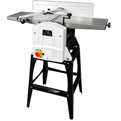
Before we dive into coding, let’s get one thing straight: programming an auto boring machine isn’t just typing numbers into a control panel. It’s translating a part’s engineering specifications into a sequence of movements that balance speed, precision, and material removal. I’ll be using our most common model, the CB-1200 (a manual-CNC hybrid we’ve supplied to 300+ small and medium machine shops across North America), to ground these steps. This machine is popular because it’s versatile enough for both small engine cylinders and large hydraulic cylinder bores, so the logic applies to most auto boring units on the market.
Step 1: Gather and Validate Part Specs (No Shortcuts Here)
The first mistake I see new operators make is grabbing a part sample and jumping straight to the control screen. Before you program anything, you need two non-negotiable documents: the part blueprint and a physical measurement of the old bore (or new part, if you’re working with a raw component). For context, when we sell a machine, we give all operators a 12-page quick-start guide, and the very first line of that guide reads: “Verify specs before entering a single code.”
Let’s say you’re programming to re-bore a 2004 V8 engine cylinder. The blueprint will list the OEM’s final bore diameter (say, 4.1250 inches), the required tolerance (±0.0005 inches—critical for piston fit), and the material: cast iron. You’ll also need the current condition of the cylinder: is it tapered? Scored? Out-of-round? I always recommend measuring the bore in at least six points (top, middle, bottom, front, back, left) across two axes. If it’s tapered by 0.003 inches, your programming will need to account for that, not just cut straight to the final diameter.
Pro tip: I keep a portable digital bore gauge in my toolbox (I’ve had this one for 15 years) and measure every job twice before starting. A spec mismatch here means you’ll waste a boring bar and a part in 10 minutes flat.
Step 2: Prepare the Machine and Tooling for Programming
Once you have your specs, you need to set up the machine so it’s ready to execute your program. This is where the CB-1200’s setup routines (and our machine’s design) make programming easier than older, fully manual units. First, level the machine’s worktable—an unlevel table can throw off your Z-axis (depth) readings by 0.001 inches per inch of table tilt, which adds up fast on long bores.
Next, install the correct boring bar and insert. For cast iron, we use solid carbide inserts—they last 10x longer than HSS inserts and deliver a cleaner finish. A common question I get from shops that switch to our machines: “Why do I need to program the tool offset instead of just measuring?” Here’s the reason: every insert wears slightly, and every boring bar has a tiny manufacturing tolerance. Programming a tool offset (you’ll enter this as a G-code parameter) accounts for that, so you don’t have to re-measure the bar every time you swap inserts.
Before opening the programming screen, run a dry cycle. This means securing a test block (or even an old cylinder) to the table, loading the tool, and running the full sequence without turning on the spindle. Watch how the X and Z axes move—make sure there’s no binding, that the tool is aligned dead-center with the bore’s axis, and that the turret stops at the correct depth. I once had a client call me panicking because his new machine’s turret was 0.002 inches off-center; he fixed it by re-calibrating the axis alignment in the control menu, which takes 2 minutes. Skipping that step would have given him hours of rework.
Step 3: Write the Core CNC Program (G-Code Made Simple)
Now we get to the actual programming part. I know G-code sounds intimidating if you’re new to CNC, but auto boring machines use a simplified set of codes tailored specifically to bore work—no complex 3D machining required. Let’s break down the core program for that V8 cylinder job, step by step, using standard G-code for our machine:
First, initialize the machine and set your units. Most shops use inches, so you’ll start with G20 (inches mode) and G90 (absolute positioning—this means all measurements are from a fixed origin, not relative to the last point you moved).
Next, define your origin point. The origin is where the tool starts, and for boring, you want it at the top of the bore, along the centerline. Enter G54 to activate the primary work offset (this is preset on our machines, but you can adjust it if needed).
Then, set your spindle speed and feed rate. For cast iron, I use S1200 (spindle speed in RPM) and F0.008 (feed rate in inches per revolution). These numbers aren’t random—too fast, and the insert will chip; too slow, and you’ll get a rough, grainy finish. Our operation manual has a chart for common materials, so I don’t have to guess.
Now, the tool path. This is the sequence that makes the cut. For a through-bore (like an engine cylinder), the path is: move the tool to just outside the top of the bore, feed it down to the start depth, then feed it along the X-axis (the direction that controls diameter) at a constant rate until it reaches the final desired diameter. For our V8 job, that’s X4.125 (the final bore diameter), moving from X0 (center) to X4.125.
Add a dwell at the end. Dwell (G04 P0.5) means the spindle stops moving forward for 0.5 seconds at the full diameter. This eliminates any step or taper at the end of the cut—super important for consistent piston seating.
Finally, retract the tool and reset. After the cut, move the tool back to X0 (center), then retract it along the Z-axis to a safe height (Z2.0, 2 inches above the part) so you can unload it.
Wait, I know what you’re thinking: that’s only one cut. What about roughing vs. finishing? Right! Most jobs need two passes: a rough cut that removes most of the material, and a finish cut that leaves the precise diameter. For our V8 job, I’d program a rough cut to 4.120 inches (leaving 0.005 inches for the finish pass) at S1000, then the finish pass at S1200 and F0.008. That small extra step makes all the difference between a part that fits perfectly and one that gets sent back.
A quick note on program names: I always name programs after the part they’re for—like V8_CYLINDER_4.125_INCH or HYD_CYL_2.500. It saves you 10 minutes of searching later when you pull up a job you did last month.
Step 4: Calibrate and Test the Program Before Full Production
Here’s where most operators skip a critical step: testing the program on a scrap part first. Even if you followed the steps exactly, machine wear or a slight spec miscalculation can throw off the cut. I always test on a leftover cylinder or a steel test block the size of a standard bore.
To calibrate, run the program on the test part, then measure the bore with a micrometer. If the measured diameter is 4.124 inches instead of 4.125, you don’t need to rewrite the whole program—just adjust the X-axis offset by 0.001 inches. For example, if your program calls for X4.125, and your test cut is 0.001 undersized, change the code to X4.126. That’s the beauty of modern auto boring machines: small, precise adjustments keep your parts within tolerance.
I once had a new machinist at a small shop test a program on a scrap part, and he noticed the bore was tapered by 0.002 inches. Turns out, his worktable was tilted 0.02 degrees—something he would have missed if he’d skipped the test. Calibration here takes 5 minutes, but saves you a $1,200 engine block.
Step 5: Save and Store Programs for Repeat Jobs
Once your program is tested and approved, save it to the machine’s control. All our auto boring machines have 1GB of internal storage, so you can save hundreds of programs, and you can back them up to a USB drive in 1 click. For repeat jobs—like the same V8 cylinder for a regular customer—this is a game-changer. I’ve had shops that saved a program for a 100mm hydraulic cylinder and used it for 50+ jobs without any adjustments.
Pro tip: Label every saved program with the part number, spec, and material. No more guessing which program is for the 3.500-inch bore vs. the 3.750-inch bore when you’re in a rush to get a job done.
Common Mistakes to Avoid (I See These Every Month)
After selling auto boring machines for 12 years, I can list the top 3 mistakes that lead to bad cuts:
- Ignoring material tolerance: Cast iron is brittle, so too high a feed rate can cause insert chipping. Aluminum, on the other hand, requires a higher speed (S1500) and lower feed to avoid building up edge material.
- Forgetting to zero the tool: Every time you swap a boring bar or insert, you need to re-zero the tool offset. I’ve seen a shop swap an insert and forget to zero, leading to a bore that was 0.01 inches oversized—ruining three parts before they caught it.
- Cutting corners on alignment: The tool must be perfectly aligned with the bore’s axis. Even a 0.001-inch offset will create a tapered cut, which is invisible at first but causes piston wear within a few thousand miles.
Final Word from Your Auto Boring Machine Supplier
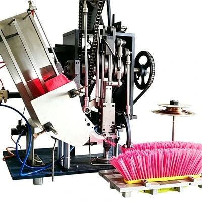
Programming an auto boring machine isn’t rocket science, but it does require attention to detail. That’s why we build our machines to simplify the process—pre-set work offsets, intuitive control screens, and step-by-step prompts for new operators—so you can spend less time troubleshooting and more time getting jobs done right.
Wood Handle Making Machine If you’re ready to upgrade your shop’s boring capabilities, or you want to learn more about our machines’ programming features, our team is here to help. Whether you’re a one-person operation or a mid-sized manufacturing facility, we’ll work with you to find the right auto boring machine and support you through every step of setup, programming, and beyond.
References
- American Machine Tools Association. (2021). CNC Machining Fundamentals: Precision Boring Operations. AMTA Press.
- SMW Autoblok. (2022). Setup and Calibration Guide for Horizontal Boring Machines. SMW Autoblok Technical Publications.
- Kennametal. (2020). Insert Selection and Cutting Parameters for Cast Iron Machining. Kennametal Manufacturing Engineering Bulletin.
Tongcheng Shengfeng Machinery Factory
As one of the most professional auto boring machine manufacturers and suppliers in China, we’re featured by quality products and good service. Please rest assured to buy durable auto boring machine for sale here from our factory. Contact us for more details.
Address: Shapu Village, Qingcao Town, Tongcheng City, Anhui Province
E-mail: 15955686317@163.com
WebSite: https://www.shengfengmachine.com/
